MODS for PCB´S
How to use the online MODS to make files to mill your own circuit boards!
Summary:
- Create and save file of circuit board traces and outcut.
- Load a program and module in MODS
- 1/64 traces files
- 1/32 holes / outcut file
- Send the files to the machine
Step 1 obtain the files: Find or Design a Circuit Board
Export/save your board design as .png, You should have two or three images, depending on your PCB:
- traces
- holes drill
- outline
As an example of an PCB this tutorial will use the new FabTinyISP others FabIsp option can be found here A handy free program to do design circuits yourself, is Eagle.
Step 2: MODS - Setup (1/64)
MODS is the new FABMODULES it more capable and works by connecting nodes to develop each process. You can customize you own workflows by loading different modules or use an already precompiled program.
In our case we are going to use a precompiled program and add a module to save automatically in our computer instead of connecting directly to the machine.
- Open mods in your browser recommended firefox/chrome
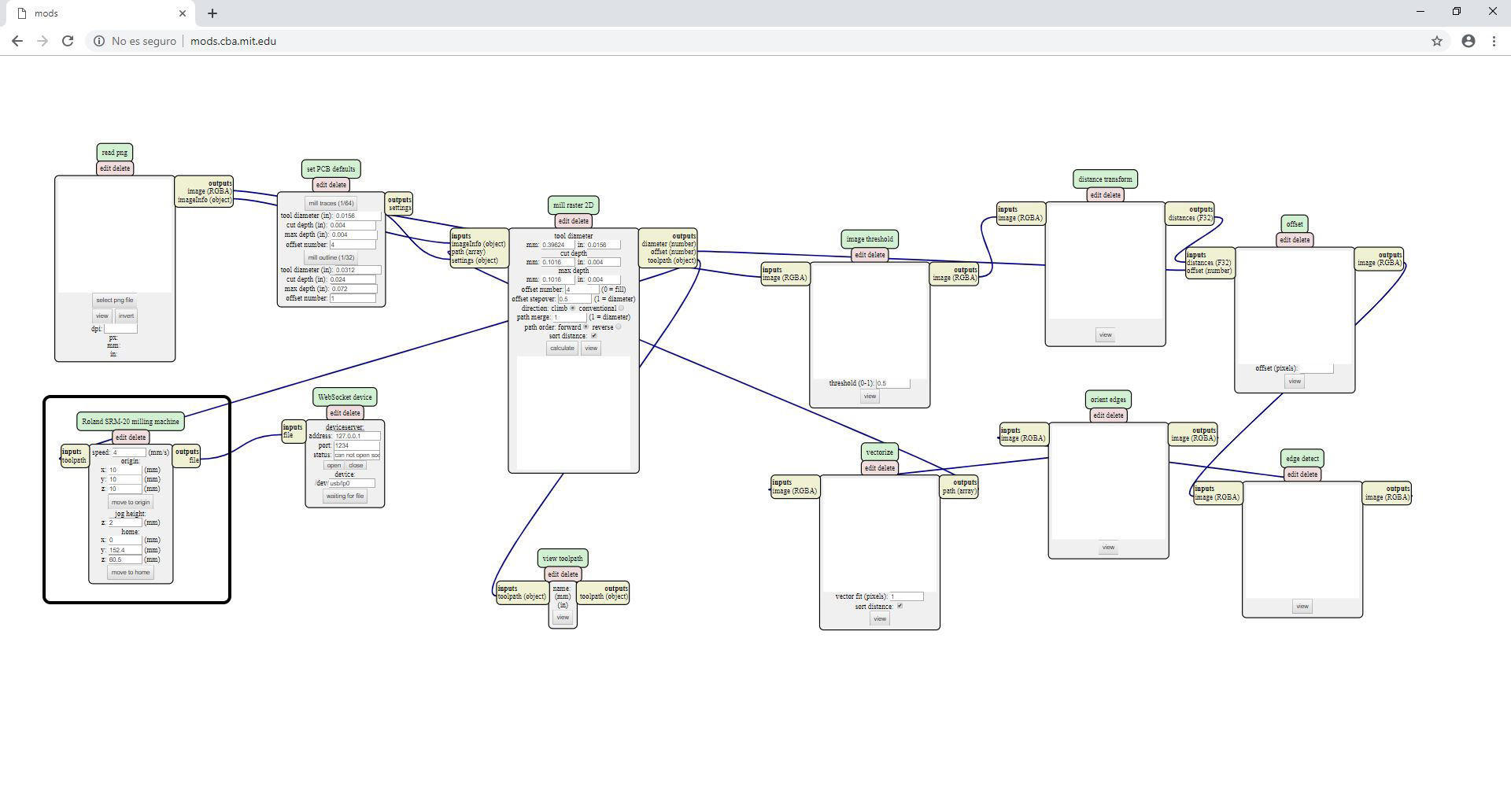
Right click anywhere and select PROGRAMS -- select OPEN SERVER PROGRAM
select ROLAND > MILL > SMR20-MDX20(choose the machine you will use) and now PCB

We need to add another module to make it save the file automatically. So we need to look for the program/component that outputs the file. In this case Roland SRM-20 milling machine
Right click anywhere in the white space and select MODULE > OPEN SERVE MODULE > SAVE FILE
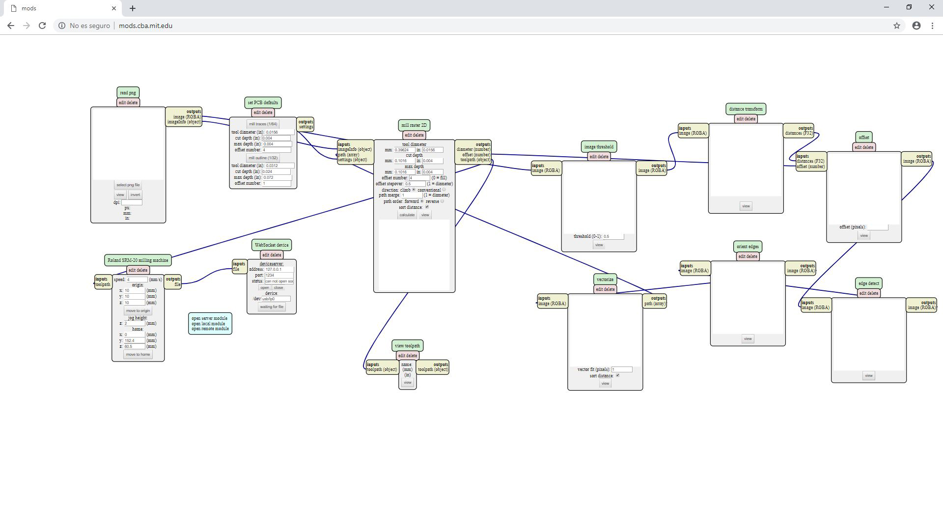
Now connect the elements by clicking on OUTPUT of RolandSrm-20milling machine and clicking again in INPUT of save file module to make the connection/ wiring between them.
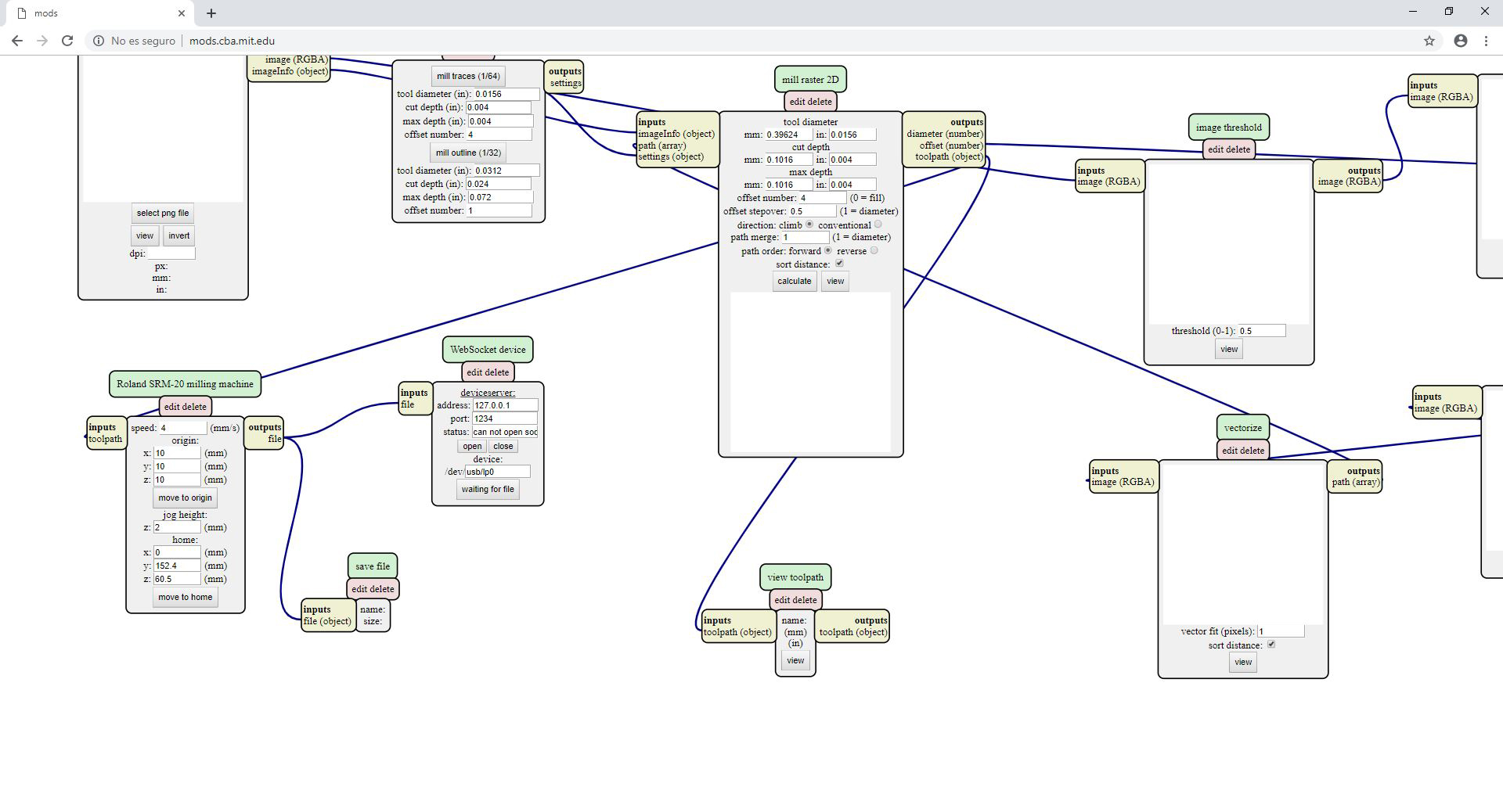
- Done!
Step 3: MODS - Traces (1/64)
Open your traces image file (This is the one with lines that will form the wires between your components.)
Go to READ PNG MODULE SELECT- PNG FILE - select your traces image
In SET PCB Default module click in MILL TRACES 1/64
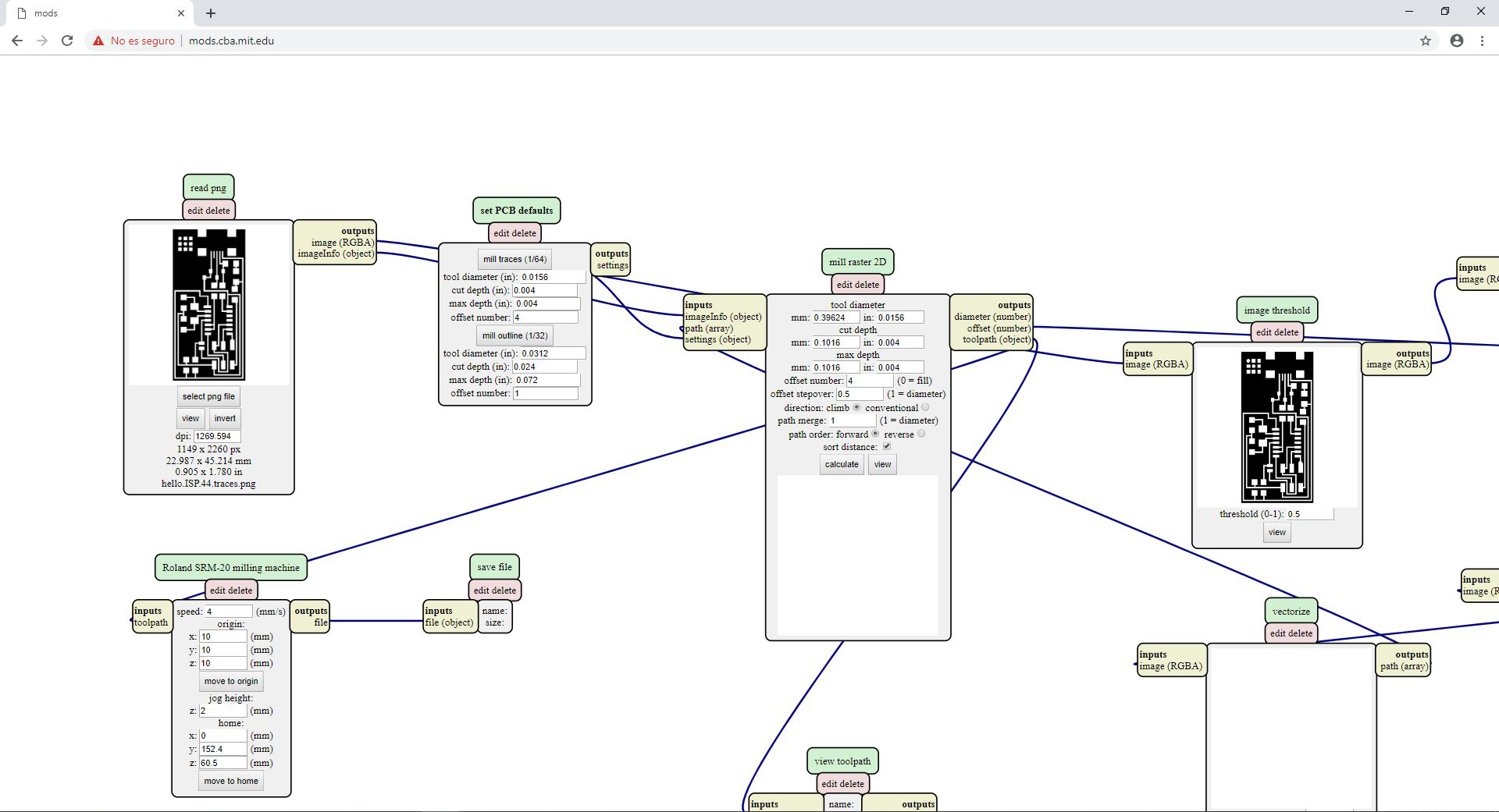
- In Mill Raster 2D module click in Calculate
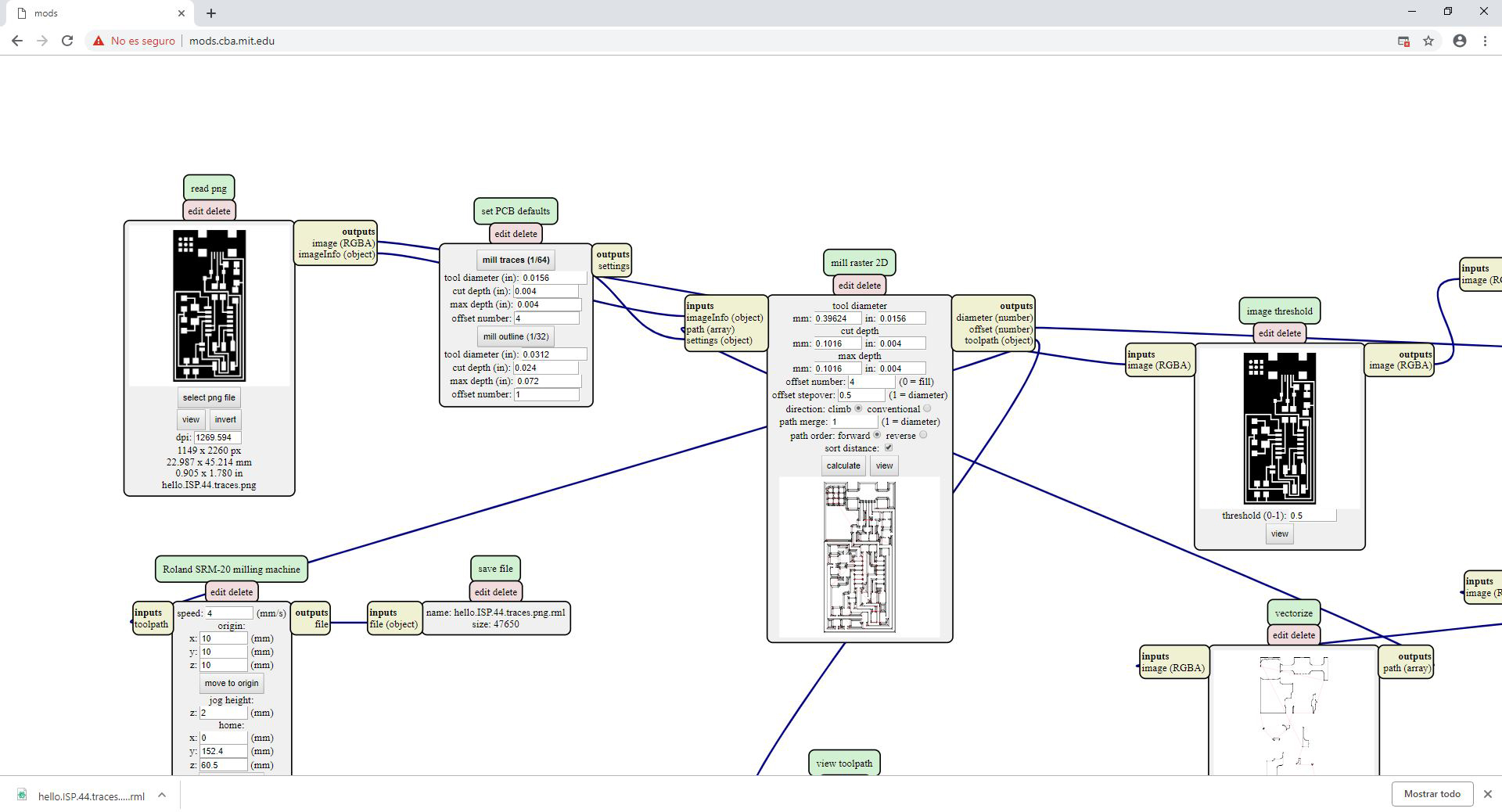
- The file will be saved automatically into your download folder.
VALUES THAT YOU CAN MODIFY
In module Roland SRM-20 milling machine Origin
- x0(mm) - 0
- y0(mm) - 0
- z0(mm) - 0 These x0,y0,z0 are for setting up an offset from the origin save in
- zjopg - 12
This is the z distance that the mill will go up between the air travellings - Speed - 4 or 3 mm/s for new end mills
x/y/x home is the parking position after finishing the cut
Step 4: MODS - Outcut/Holes (1/32)
Open your traces image file (This is the one with lines that will form the wires between your components.)
Go to READ PNG MODULE SELECT- PNG FILE - select your traces image
In SET PCB Default module click in MILL TRACES 1/32
- In Mill Raster 2D module click in Calculate
- The file will be saved automatically into your download folder.
- x0(mm) - 0
- y0(mm) - 0
- z0(mm) - 0
- zjopg - 12
- Speed - 0.5
Click "calculate"(you will see the path calculating), when the process will finish it will "automatically be saved into your downloads folder"
Step 5: SEND THE FILES TO A ROLAND CNC
As an guide on how to send the files you just produced in PCB this tutorial you can follow the next tutorial if you have a Roland SRM-20 o in case you have Roland MDX-20follow this one
Original tutorial by:
- Eduardo Chamorro, Fab Lab Barcelona 02.2019
Licensed under a Commons Attribution 4.0 International License