PCBs with Roland MDX-20
How to use the fab module for Roland Modela (MDX-20) to make files and mill your own circuit boards!
Summary:
- Turn on Modela, turn on the windows computer near it. Connect if needed.
- Create and save file of circuit board traces and outcut.
- Physically load circuit board and 1/64” endmill to Modela.
- Find zero for x, y, and z. Set settings on the computer to mill then send to Modela.
- Mill your PCBs
- Remove board, cut out if desired, cut apart any areas that didn’t make it.
- Finally, solder your components to your freshly made board!
Step 1 obtain the files:: Find or Design a Circuit Board
Export/save your board design as .png, You should have two or three images, depending on your PCB:
- traces
- holes drill
- outline
As an example of an PCB this tutorial will use the new FabTinyISP others FabIsp option can be found here A handy free program to do design circuits yourself, is Eagle.
Design your circuit on Fritzing or Eagle. File > Export > PNG with black background (and white fill for the circuit). The dpi should be 500.
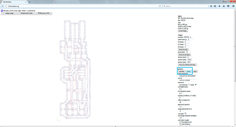
Step 2: fab modules - Traces (1/64)
Open fab modules in your browser recommended firefox/chrome Open your traces image file (This is the one with lines that will form the wires between your components.)
- input format - PNG - select your traces image
- output format - roland mill (.rml)
- process - PCB traces (1/64)

Always check the real size and resolution of your board.
- Machine - MDX-20
- x0(mm) - 0
- y0(mm) - 0
- z0(mm) - 0 These x0,y0,z0 are for setting up an offset from the origin save in V-Panel
- zjopg - 12
- Speed - 4 or 3 mm/s for new end mills
x/y/x home is the parking position after finishing the cut
Click "calculate"
Now you can see the tool path (blue lines for cut,red for movements in the air), this should outline all your traces. Iterate your design if you see something wrong with them.
and after "save"
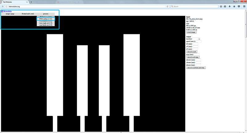
Step 3: fab modules - Outcut/Holes
Refresh fab modules
Now your outline/holes image file
- input format - PNG - select your traces image
- output format - roland mill (.rml)
- process - PCB outline (1/32)
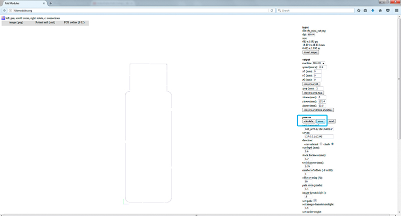
Always use the same x0,y0,zO that you used for the trace files or both cuts will not match.
- Machine - MDX-20
- x0(mm) - 0
- y0(mm) - 0
- z0(mm) - 0
- zjopg - 12
- Speed - 0.5
Click "calculate"(you should see a blue path) and after "save"
Step 4: Sending the traces!
For interfacing to the machine we are going to usa a custom compiled software for the fabacademy.It is a processing sketch that can be found already precompiled. DOWNLOAD MODELA MDX20 INTERFACE-SIMPLIYFAB20
- Swith on the machine, by defect the MDX20 goes to view mode to show you the cutting bed.
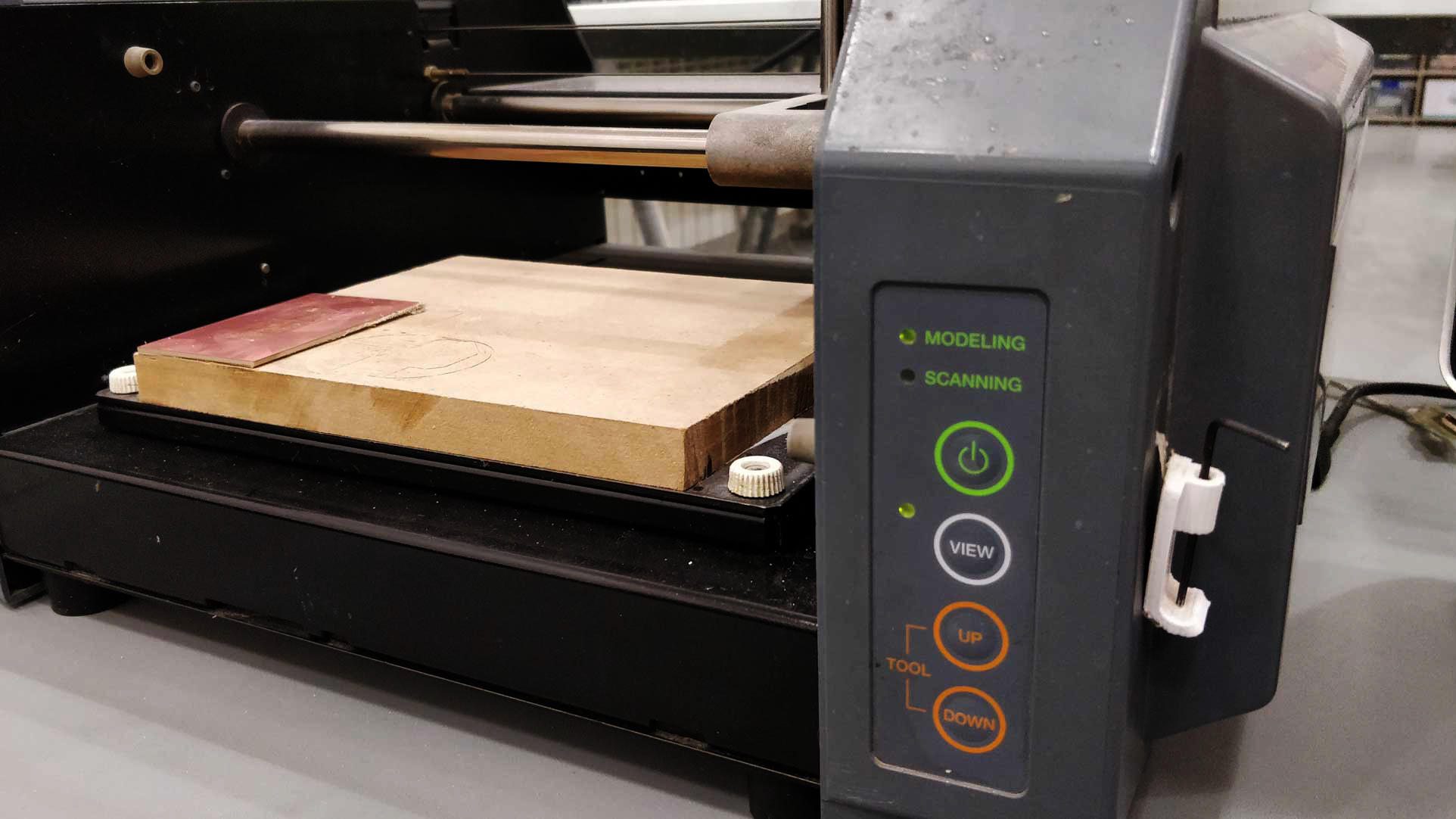
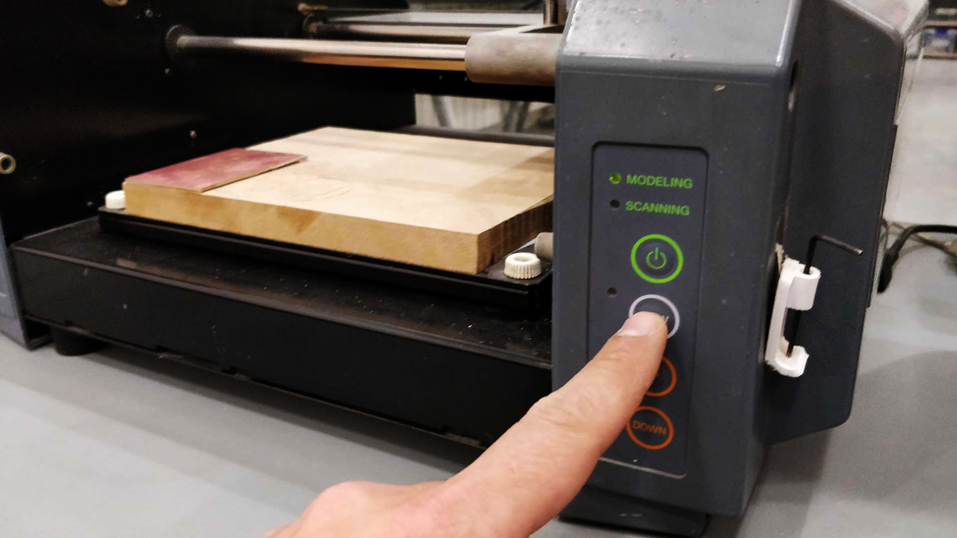
You need to click view to be able to start sending files.
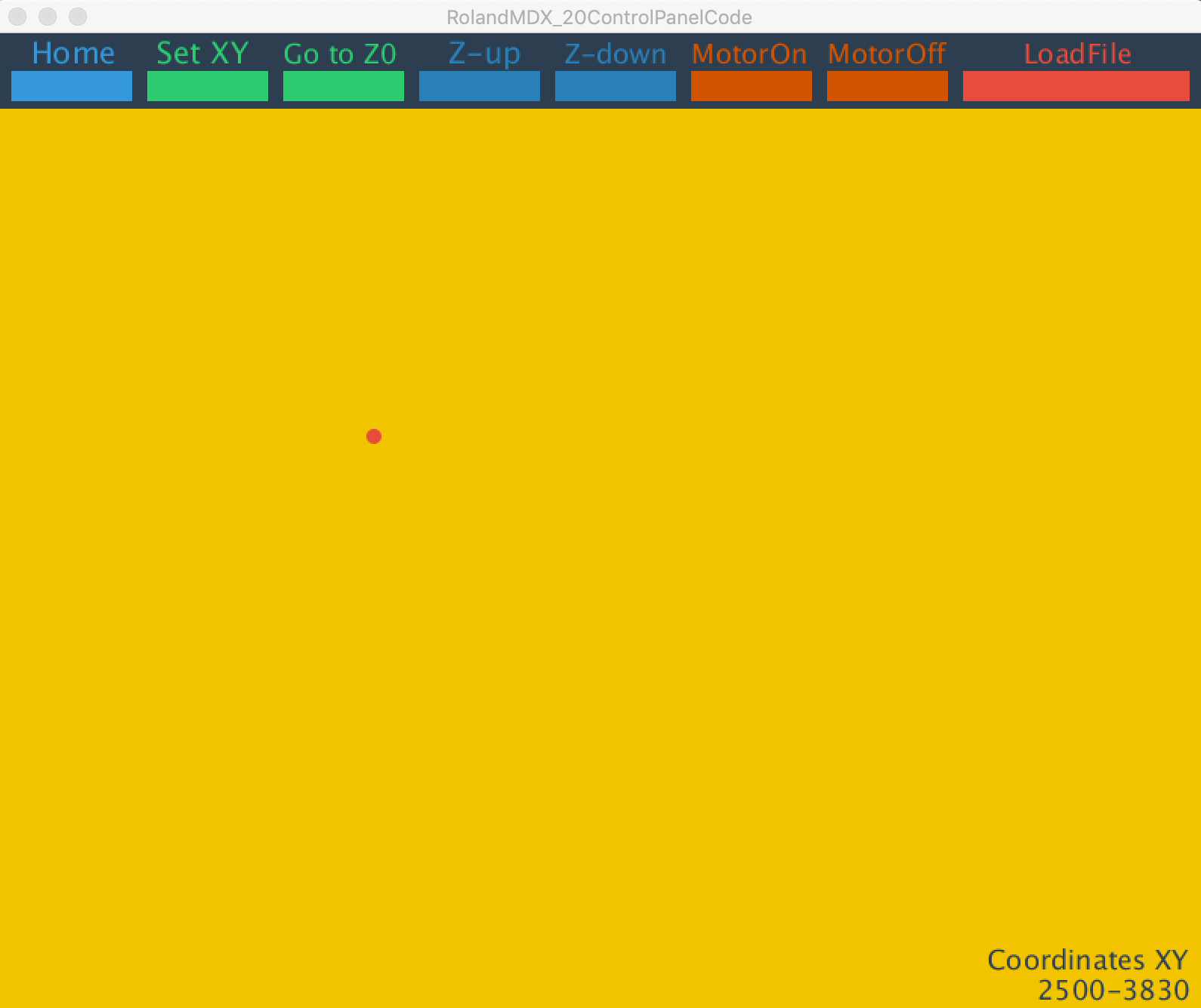
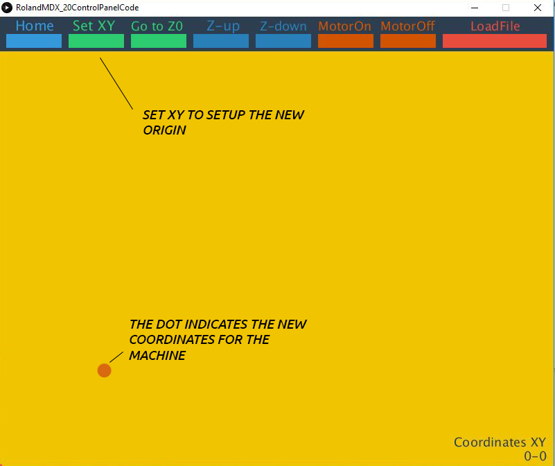
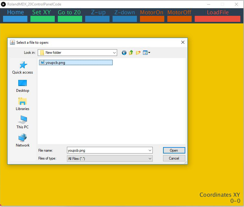
- Open RolandMDX_20ControlPanel.pde or the compiled program version RolandMDX_20ControlPanel
- Move the spindle position by clicking on the yellow window( it is the machine bed/working space)
- Once you get to your desired position select SET XY to set the origin for XY
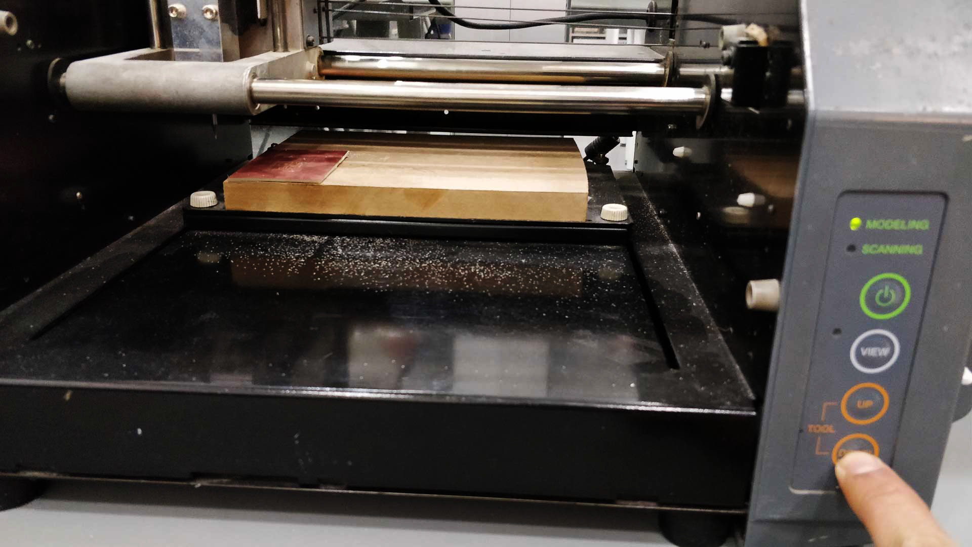
- To setup the Z position we have to move mill bit manually with the machine UP/DOWN buttons(located on the front of the machine).I recommend doing it with the spindle on until touching the PCB plate The Z is not setup on the sofware but with the hardware buttons..The machine don´t remember the Z position setup with the interface buttons up/down.
- Select your file with the LOADFILE button and press enter to start cutting.
Note that the z-zero makes more of a difference for milling than for drilling.
Step 7: Send the outcut/holes!
When the machine stops, you will have to vacuum to see the traces.Do not remove the board!
- Now we are going to repeat the same Z origin procedure but before we have to change the end mill to use the 1/32 end mill.
- After zeroing the Z, following the same steps as in the traces cut, send the file by selecting it in "LOADFILE" again in the control panel but now choose your Outcut/Holes files and press enter to start cutting.
Only set the origin Z or you will not be able to match the last origin X/Y
When the machine stops,remove your board with the help of a spatula,don't be Hulk or you will break the board.Vacuum away the plastic and metal chips in the area. Enjoy your PCB and Clean your mess and files after you're done working!
--
Troubleshooting
Nothing happens when I send the rml over.
- Make sure the transparent cover is placed properly on the roland machine - there's a sensor/switch that prevents the drill from spinning if the cover is not placed properly.
- Also make sure the light next to the VIEW button on the roland machine is off. Press the button to toggle it.( This button is for bringing the platform closer to the user and the machine enters pause mode)
- If the green VIEW light is on, it anything you send will be stored in buffer and it will execute when set right (this can be annoying).
One of the LEDs is blinking angrily
- If one of the LEDs blink very fast it's likely that something went wrong and you might have to stop sending RML, turn off and on the machine and re-send the RML file. If it persists, something isn't being done right - check the guide carefully.
- A known cause for this is the roland machine is receiving too many messages before being able to execute (each line in the RML file is sent every two seconds by the processing sketch - if the drill cannot keep up, the LED blinks really fast).
I checked the code and it send the command slowly
- The processing sketch can be smarter - eg. there's currently a second delay between each line sent from the rml file to ensure we don't flood the roland machine with all commands at once.
--
Tools Needed
Mill Bits
- Micro milling bit for PCB for the traces cut (0.0156" DIA 2FL SE AlTiN 1/64).1/64 Flat Endmill
- Micro milling bit for PCB for the traces outcut and holes(0.0312" DIA 2FL SE AlTiN 1/32).1/32 Flat Endmill
MDX 20 ROLAND
- With the proper collet for the endmills and the serial adapter cable.
--
References
- Fab modules, how to make circuits on the Modela milling machine, also a good resource to setup and problem shoot the Modela.
- Media Lab Helsinki, making PCB with Roland Modela MDX-20 (Eagle version). The website including rml guidelines and more are available as .zip file for download. The tutorial uses the Eagle layout editor to design PCBs. If you're using Fritzing, this is the guide.
- bringing a 12 year old Roland MDX-20 up to date
- .rml or .rml-1 format to instruct a Modela milling machine. RML-1 Programming Guide
- sending rml to mdx-20 on unix
- Roland circuit board milling
- Roland Command guide
-- Original tutorial by:
- Eduardo Chamorro, Fab Lab Barcelona 02.2019
Licensed under a Commons Attribution 4.0 International License